Condensate Drain Pipe U Trap Calculation

From Unvented Traps To Inadequate Drain Slopes A Building Inspector Picks His Top 10 In The World Of P Plumbing Installation Residential Plumbing Diy Plumbing
Time To Reconsider Use Of P Traps For Condensate Removal Hpac Engineering

How To Make U Trap For Condensate Drain Plumbing Fcu Drainage Air Conditioning Engineering Youtube

S Trap Google Search Bathroom Plumbing Plumbing Installation Plumbing Drains

Can A Laundry Sink Drain Be Installed Without A Trap Under It In 2020 Laundry Sink Sink Drain Laundry Room Sink

How To Fix A Toilet Heating And Plumbing Plumbing Installation Plumbing Repair

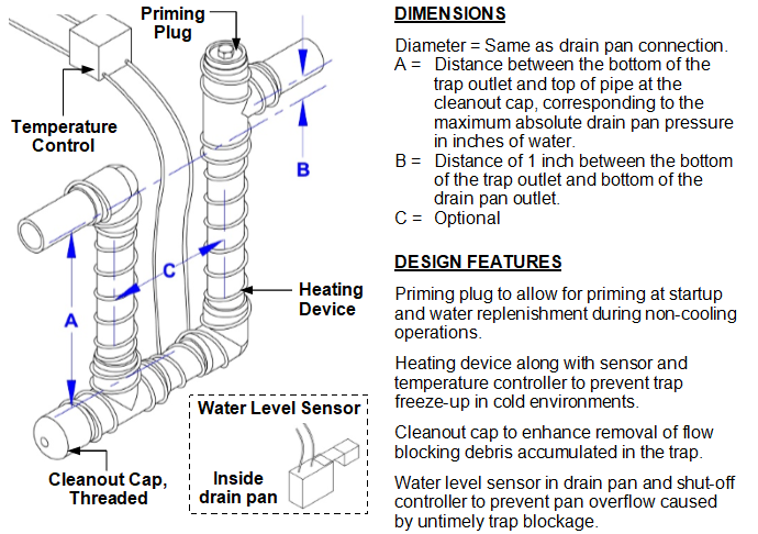
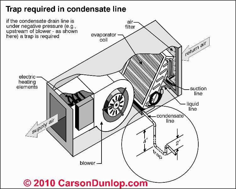
Current drain systems condensate drain systems accepted as the industry standard include water traps like the one shown in figure 2.
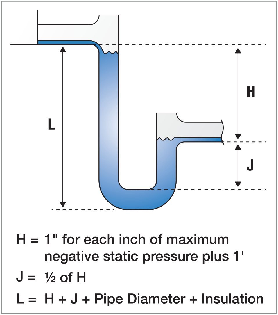
Condensate drain pipe u trap calculation.

Condensate Drain Calculation Lab Ahu Heating Ventilating And Air Conditioning Electromechanical Engineering

Pin On Plumbing
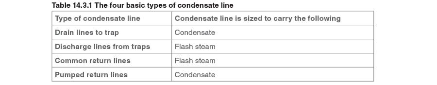
Sizing Condensate Return Lines Spirax Sarco
Hvac P Trap Design Maintenance Csi Specification
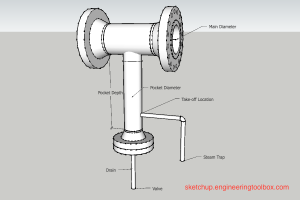
Steam Pipes Installation Of Drip Legs

Pin On Plumbing

Pin On Cabin

Washing Machine P Trap And Drain Plumbing Diy Home Improvement Plumbing Installation Plumbing Diy Plumbing

Calculating Duct Size Hvac Design Duct Design
Z D9thf7ege Rm

Waterless Trap Condensate Trap Air Trap N Series Negative Pressure Des Champs Technologies

Codes Dictate The Proximity Of Vents To Drains And The Rules Should Never Be Ignored If The Vent Is T Residential Plumbing Plumbing Installation Pex Plumbing

Iapmo

Steam Mains And Drainage Spirax Sarco
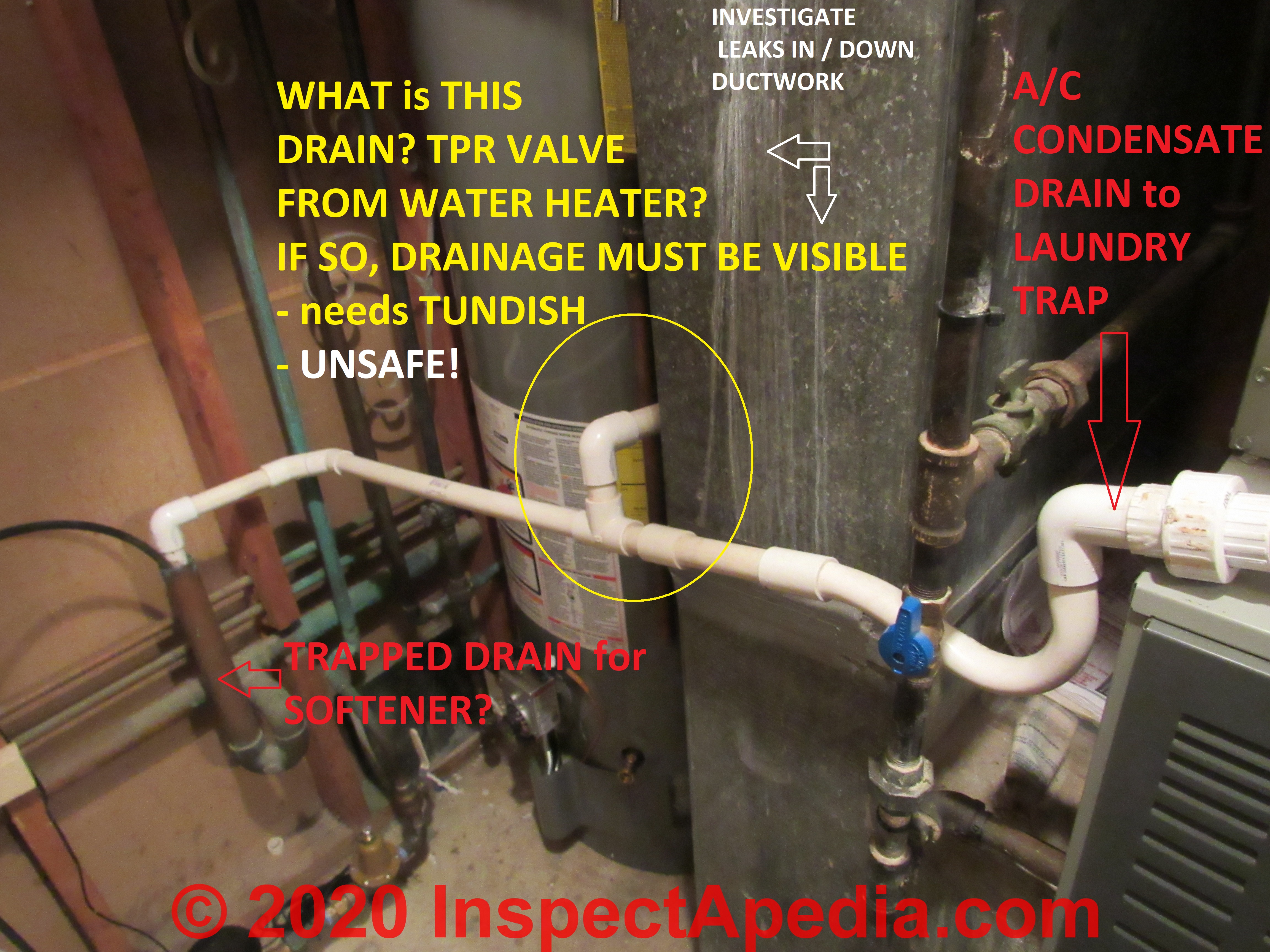
A C System Condensate Drains Condensate Piping Condensate Pumps Inspect Diagnose Repair Guide

How A House Works A Simple Plumbing Diagram Of Traps And Vents Diy Plumbing Plumbing Home Maintenance

Toilet Drain Plumbing How To Fixture Drain House Simple For Toilet Plumbing Do It Yourself Plumbing Vent Plumbing Installation Diy Plumbing

Pin On Cad Plumbing
1

Plumbing Diagram Kosmeticheskij Remont Vannoj Komnaty Santehnika Remont Doma

Why Do I Need Refrigerant Traps In My Piping

Khyfv Png 426 284 Plumbing Vent Bathroom Addition Sink Drain

Bellows Steam Trap Steam Traps Bellows

Quickly Unclog Bathroom Sink Using No Chemicals Unclog Bathroom Sinks Bathroom Sink Clogged Sink Bathroom
Source : pinterest.com
